| |
| META TOPICPARENT |
name="WebHome" |
%DASHBOARD{ section="banner" |
| | |
|
<
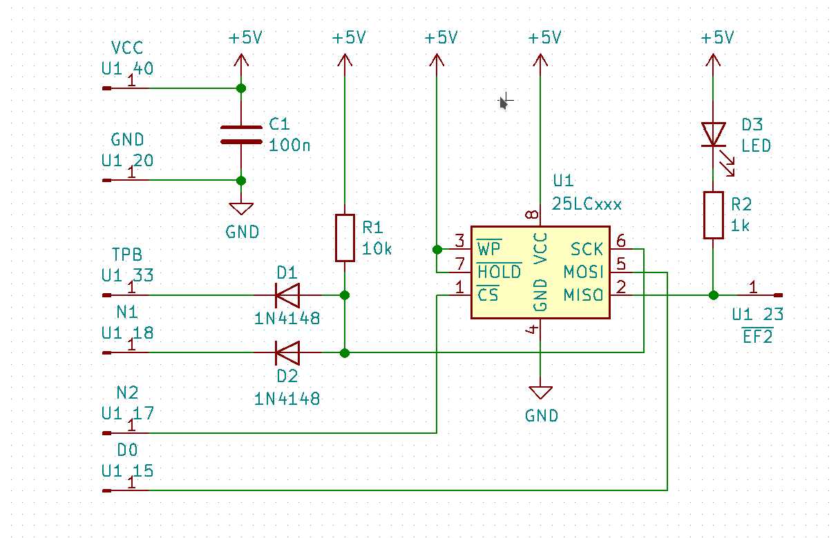
< | The Serial Peripheral Interface SPI or four-wire serial bus is easy to use. The CDP1802 (MC) is the SPI master, the EEPROM is the slave. There are many different EEPROM types and sizes available e.g. AT25M02 (2Mbit, 256 KiB, $3), 25LC1024 (128 KiB, $2), or 25LC512 (64 KiB, $1.50). All available in DIL8 packages. 64/128/256 KiB seems very small for today's standards where storage is quantified in GiB, but I think it's more than enough for a small Forth system, the size is similar to early floppy disks. If you want more memory there is 16 MiB serial EEPROM W25Q128J from WINBOND, please note that is a 3.3 V device! or four-wire serial bus is easy to use. The CDP1802 (MC) is the SPI master, the EEPROM is the slave. There are many different EEPROM types and sizes available e.g. AT25M02 (2Mbit, 256 KiB, $3), 25LC1024 (128 KiB, $2), or 25LC512 (64 KiB, $1.50). All available in DIL8 packages. 64/128/256 KiB seems very small for today's standards where storage is quantified in GiB, but I think it's more than enough for a small Forth system, the size is similar to early floppy disks. If you want more memory there is 16 MiB serial EEPROM W25Q128J from WINBOND, please note that is a 3.3 V device! |
>
> | The Serial Peripheral Interface SPI or four-wire serial bus is easy to use. The CDP1802 (MC) is the SPI master, the EEPROM is the slave. There are many different EEPROM types and sizes available e.g. AT25M02 (2Mbit, 256 KiB, $3), 25LC1024 (128 KiB, $2), or 25LC512 (64 KiB, $1.50). All available in DIL8 packages. 64/128/256 KiB seems very small for today's standards where storage is quantified in GiB, but I think it's more than enough for a small Forth system, the size is similar to early floppy disks. If you want more memory there is 16 MiB serial EEPROM W25Q128J from WINBOND, please note that is a 3.3 V device! |
| |
CLK   MC ->- host
MOSI MC ->- host |
| | While in Hold mode, the SO pin will be in a high impedance state. In addition, both the SI pin and the SCK pin
will be ignored. |
|
>
> | From 1024 Kibit up there are 24 address bits, 8 Kibit to 512 Kibit have 16 address bits. 1, 2, and 4 Kibit have 8 bit address bits. |
| | 25LCxxxx Instruction Set
|
| | |
|
<
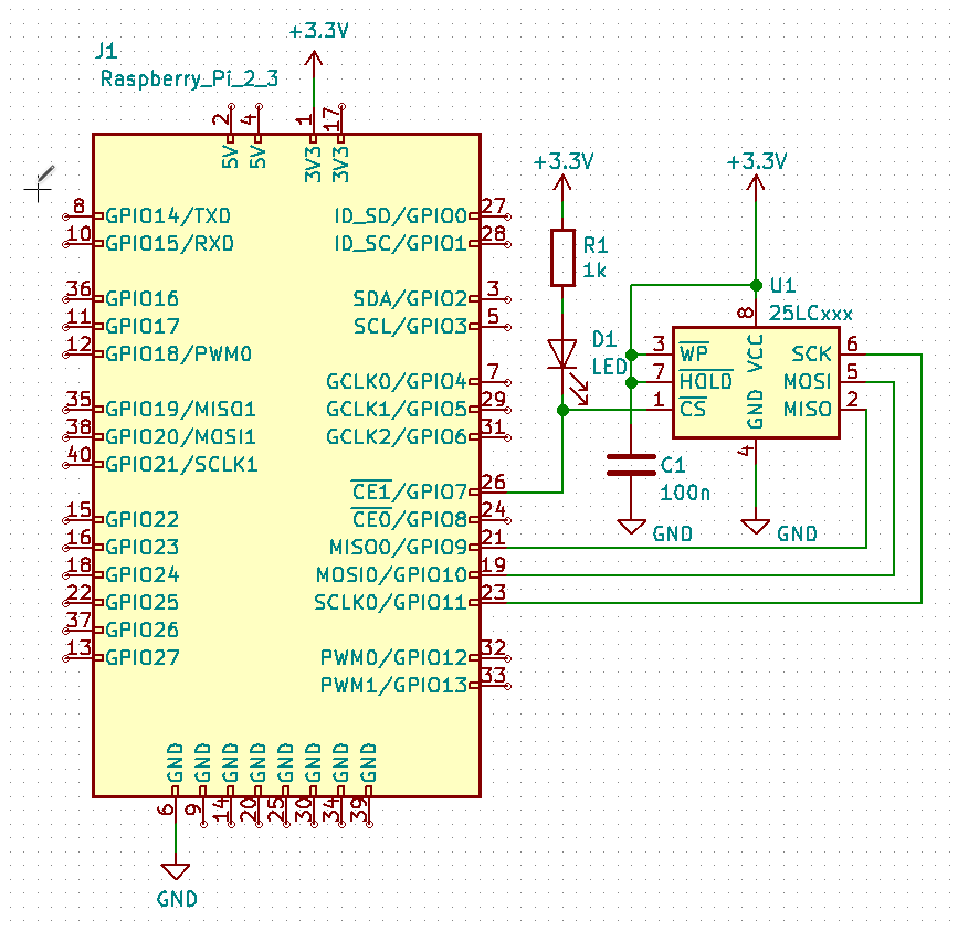
< | http://www.netzmafia.de/skripten/hardware/RasPi/RasPi_SPI.html |
>
> | |
| |
|
|
<
< |
| SPI0 MISO |
9 |
IN4 |
| SPI0 MOSI |
10 |
IN3 |
| SPI0 SCLK |
11 |
IN6 |
|
>
> |
| SPI0 MISO |
9 |
IN4 |
| SPI0 MOSI |
10 |
IN3 |
| SPI0 SCLK |
11 |
IN6 |
|
| |
|
|
<
< |
|
>
> |
| SPI0 CS1 |
7 |
O0 |
| EEPROM CS |
5 |
O1 |
|
| |
| SPI1 MISO |
19 |
O5 |
| SPI1 MOSI |
20 |
- |
| SPI1 SCLK |
21 |
shutdown |
|
| |
|
|
<
< | |
>
> | |
| | |
|
<
< | Read Byte |
>
> | Because of: "A high-to-low transition on the CS pin is required to start an operation and a low-to-high transition is required to end an operation." That means the CS has to be active as long as a read or write process is going on. Therefore the SPI0 CSx can't be used.
eeprom2bin (download tool)
- NAME
- eeprom2bin - Copies the EEPROM memory to a binary file on the Raspberry Pi.
- SYNOPSIS
- eeprom2bin [-s hexadr] [-e hexadr] [file]
- DESCRIPTION
- Copies the EEPROM memory to a binary file (or stdout) on the Raspberry Pi. The Raspberry Pi GPIO SPI0.1 is used as interface to the SPI EEPROM (24 bit address, at least a 1024 Kibit type, 256 byte page). The generated data is written to the standard output stream or to a file. Caution: Overwrite file if it exists. Use > for redirecting (save the file) or | for piping to another command (e.g. hexdump).
- OPTIONS
- Non argument options that are duplicated on the command line are not harmful. For options that require an argument, each duplication will override the previous argument value.
- -s hexadr
- start address in hex (0 is default)
- -e hexadr
- end adress in hex (0x1FFFF is default)
bin2eeprom (upload tool)
- NAME
- bin2eeprom - Copies the content of binary file on the Raspberry Pi to EEPROM.
- SYNOPSIS
- bin2eeprom [-s hexadr] [-e hexadr] [file]
- DESCRIPTION
- Copies the content of binary file on the Raspberry Pi to EEPROM memory. The Raspberry Pi GPIO SPI0.1 is used as interface to the SPI EEPROM (24 bit address, at least a 1024 Kibit type, 256 byte page). Use < for redirecting or | for piping from another command.
- OPTIONS
- Non argument options that are duplicated on the command line are not harmful. For options that require an argument, each duplication will override the previous argument value.
- -s hexadr
- start address in hex (0 is default)
- -e hexadr
- end adress in hex (0x1FFFF is default)
|
| | |
|
<
< | Write Byte |
| |
|
| | Comments
\ No newline at end of file |
|
>
> |
| META FILEATTACHMENT |
attachment="raspi-eeprom.png" attr="" comment="" date="1548535017" name="raspi-eeprom.png" path="raspi-eeprom.png" size="25608" user="PeterSchmid" version="2" |
|