Difference: BoardSupportPackageH743 (12 vs. 13)
Revision 132022-06-30 - PeterSchmid
| Line: 1 to 1 | ||||||||||||||||||||||||||||
|---|---|---|---|---|---|---|---|---|---|---|---|---|---|---|---|---|---|---|---|---|---|---|---|---|---|---|---|---|
Board Support Package for the STM NUCLEO-H743ZI Board
Intro
DRAFT
The board support package for the STM NUCLEO-H743ZI
Contents
Overview
Board Support Words
led1!        ( n -- )    sets LED1 (green)
led2!        ( n -- )    sets LED2 (yellow)
led3!        ( n -- )    sets LED3 (red)
led1@        ( -- n )    gets LED1 (green)
led2@        ( -- n )    gets LED2 (yellow)
led3@        ( -- n )    gets LED3 (red)

switch1?     ( -- n )    gets switch1 (button A), closed=TRUE
dport!       ( n -- )    sets the digital output port (D0=bit0 .. D15=bit15).
dport@       ( -- n )    gets the digital input/output port (D0=bit0 .. D15=bit15).
dpin!        ( n a -- )  sets the digital output port pin a (D0=0 .. D15=15, A0=16 .. A6=23)
dpin@        ( a -- n )  gets the digital input/output port pin a
dmod         ( u a -- )  sets the pin mode: 0 in, 1 in pull-up, 2 in pull-down, 3 out push pull, 4 out open drain,
                                            5 out push pull PWM, 6 input capture, 7 output compare, 8 I2C, 9 USART, 10 analog

EXTImod      ( u a -- )  Sets for pin a (D11, D12, D13) the EXTI mode u: 0 rising, 1 falling, 2 both edges, 3 none
EXTIwait     ( u a -- )  Wait for EXTI interrupt on pin a (D11, D12, D13), timeout u in [ms]

pwmpin!      ( u a -- )  sets the digital output port pin a (D3=3, D4=4, D5=5, D6=6, D9=9, and D10=10) to a PWM value u (0..1000).
                           Default frequency is 1 kHz, TIMER3/TIMER4
| ||||||||||||||||||||||||||||
| Changed: | ||||||||||||||||||||||||||||
| < < | pwmprescale ( u -- ) Sets the PWM prescale for TIMER3/TIMER4. 42 kHz / prescale, default 42 -> PWM frequency 1 kHz | |||||||||||||||||||||||||||
| > > | pwmprescale ( u -- ) Sets the PWM prescale for TIMER3/TIMER4. 60 kHz / prescale, default 60 -> PWM frequency 1 kHz | |||||||||||||||||||||||||||
| Changed: | ||||||||||||||||||||||||||||
| < < | ICOCprescale ( u -- ) Sets the input capture / output compare prescale for TIMER2. default 42 -> 42 MHz / 42 = 1 MHz, timer resolution 1 us | |||||||||||||||||||||||||||
| > > | ICOCprescale ( u -- ) Sets the input capture / output compare prescale for TIMER2. default 60 -> 60 MHz / 60 = 1 MHz, timer resolution 1 us | |||||||||||||||||||||||||||
ICOCperiod! ( u -- ) Sets the input capture / output compare (TIMER2) period. default $FFFFFFFF (4'294'967'295).
When the up counter reaches the period, the counter is set to 0.
For prescale 32 the maximum time is about 1 h 11 m
ICOCcount! ( -- u ) Sets the input capture / output compare counter for TIMER2
ICOCcount@ ( u -- ) Gets the input capture / output compare counter for TIMER2
ICOCstart ( -- ) Starts the ICOC period
ICOCstop ( -- ) Stops the ICOC period
OCmod ( u a -- ) Sets for pin a (D0, D1) the Output Compare mode u: 0 frozen, 1 active level on match,
Using the Digital Port Pins (Input and Output)Set 8 port pins to push/pull output3 15 dmod \ set D15 (SCL) to Output 3 5 dmod \ set D5 to Output 3 6 dmod \ set D6 to Output 3 9 dmod \ set D9 to Output 3 10 dmod \ set D10 to Output 3 11 dmod \ set D11 to output 3 12 dmod \ set D12 to output 3 13 dmod \ set D13 to outputremap D15, D5, .. D13 create port-map 15 , 5 , 6 , 9 , 10 , 11 , 12 , 13 , : pin ( n -- n ) \ gets the Dx pin number cells port-map + @ ;
3 16 dmod   \ set A0 to Output
3 17 dmod   \ set A1 to Output
3 18 dmod   \ set A2 to Output
3 19 dmod   \ set A3 to Output
3 20 dmod   \ set A4 to Output
3 21 dmod   \ set A5 to output
3 2 dmod    \ set D2 (SCK) to output
3 4 dmod    \ set D4 (MOSI) to output
remap D15, D5, .. D13 create port-map 16 , 17 , 18 , 19 , 20 , 21 , 2 , 4 , | ||||||||||||||||||||||||||||
| Changed: | ||||||||||||||||||||||||||||
| < < | apin@ ( a -- u ) returns the ADC value (12 bit, 0 .. 4095) from one of the analog pins A0 to A5 (0 .. 5). Here I use the A0 to control the neopixel blue led brightness. | |||||||||||||||||||||||||||
| > > | apin@ ( a -- u ) returns the ADC value (16 bit, 0 .. 65535) from one of the analog pins A0 to A5 (0 .. 5). Here I use the A0 to control the neopixel blue led brightness. | |||||||||||||||||||||||||||
: neo-blue ( -- ) begin | ||||||||||||||||||||||||||||
| Changed: | ||||||||||||||||||||||||||||
| < < | 0 apin@ 16 / neopixel! | |||||||||||||||||||||||||||
| > > | 0 apin@ 256 / neopixel! | |||||||||||||||||||||||||||
10 osDelay drop
key? until
key drop
;
Control the Knightrider Pace | ||||||||||||||||||||||||||||
| Changed: | ||||||||||||||||||||||||||||
| < < | apin@ ( a -- u ) returns the ADC value (12 bit, 0 .. 4095) from one of the analog pins A0 to A5 (0 .. 5). Here I use the A0 to control the delay. | |||||||||||||||||||||||||||
| > > | apin@ ( a -- u ) returns the ADC value (12 bit, 0 .. 65535) from one of the analog pins A0 to A5 (0 .. 5). Here I use the A0 to control the delay. | |||||||||||||||||||||||||||
| ||||||||||||||||||||||||||||
| Changed: | ||||||||||||||||||||||||||||
| < < | 0 apin@ 10 / osDelay drop \ delay depends on A0 | |||||||||||||||||||||||||||
| > > | 0 apin@ 160 / osDelay drop \ delay depends on A0 | |||||||||||||||||||||||||||
| ||||||||||||||||||||||||||||
| Changed: | ||||||||||||||||||||||||||||
| < < | 0 apin@ 10 / osDelay drop \ delay depends on A0 | |||||||||||||||||||||||||||
| > > | 0 apin@ 160 / osDelay drop \ delay depends on A0 | |||||||||||||||||||||||||||
| Changed: | ||||||||||||||||||||||||||||
| < < | The 16 bit timers TIM3 (D5 and D6) and TIM4 (D9, D10, D14, and D15) are used for the timebase, time resolution is 1 us (42 MHz SysClk divided by 42). The PWM scale is from 0 (0 % duty cycle) to 1000 (100 % duty cycle), this results in a PWM frequency of 1 kHz. If you need higher PWM frequencies, decrease the divider and/or the scale. | |||||||||||||||||||||||||||
| > > | The 16 bit timers TIM1 (D3, D4, D5 and D6) and TIM4 (D9, D10) are used for the timebase, time resolution is 1 us (60 MHz SysClk divided by 60). The PWM scale is from 0 (0 % duty cycle) to 1000 (100 % duty cycle), this results in a PWM frequency of 1 kHz. If you need higher PWM frequencies, decrease the divider and/or the scale. | |||||||||||||||||||||||||||
| Changed: | ||||||||||||||||||||||||||||
| < < | PWM port pins: D5 (TIM3CH2), D6 (TIM3CH1), D9 (TIM4CH3), D10 (TIM4CH4), D14 (TIM4CH2), and D15 (TIM4CH1). | |||||||||||||||||||||||||||
| > > | PWM port pins: D3 (TIM1CH2), D4 (TIM1CH1), D5 (TIM1CH3), D6 (TIM1CH4), D9 (TIM4CH2), D10 (TIM4CH1). | |||||||||||||||||||||||||||
| Changed: | ||||||||||||||||||||||||||||
| < < | Simple test program to set brightness of a LED on pin D6 with a potentiometer on A0. Default PWM frequency is 1 kHz (prescaler set to 42). You can set the prescale with the word pwmprescale from 42 kHz (value 1) down to 0.5 Hz (64000). | |||||||||||||||||||||||||||
| > > | Simple test program to set brightness of a LED on pin D6 with a potentiometer on A0. Default PWM frequency is 1 kHz (prescaler set to 60). You can set the prescale with the word pwmprescale from 60 kHz (value 1) down to 0.5 Hz (64000). | |||||||||||||||||||||||||||
5 6 dmod   \ set D6 to PWM

: pwm ( -- )
  begin
    0 apin@  4 /  6 pwmpin!
    10 osDelay drop
    key?
  until
  key drop
;
Control an RC Servohttps://en.wikipedia.org/wiki/Servo_(radio_control | ||||||||||||||||||||||||||||
| Changed: | ||||||||||||||||||||||||||||
| < < | The BSPs default PWM frequency is 1 kHz, 50 Hz is 20 times slower. The divider is therefore 42 * 20 = 840. | |||||||||||||||||||||||||||
| > > | The BSPs default PWM frequency is 1 kHz, 50 Hz is 20 times slower. The divider is therefore 60 * 20 = 1200. | |||||||||||||||||||||||||||
| ||||||||||||||||||||||||||||
| Changed: | ||||||||||||||||||||||||||||
| < < | 840 pwmprescale | |||||||||||||||||||||||||||
| > > | 1200 pwmprescale | |||||||||||||||||||||||||||
5 5 dmod \ set D5 to PWM
: servo ( -- )
begin
130 40 do
i 5 pwmpin!
i neopixel!
i 40 = if
1000 \ give some more time to get back
else
200
then
osDelay drop
10 +loop
key? until
key drop
;
Using Input Capture and Output CompareTime BaseDefault timer resolution is 1 us. The 32 bit TIMER2 is used as time base for Input Capture / Output Compare. For a 5 s period 5'000'000 cycles are needed. All channels (input capture / output compare) use the same time base.
: period ( -- )
  5000000 ICOCperiod! \ 5 s period
  ICOCstart
  begin
     waitperiod
     cr .time
  key? until
  key drop
;
Output CompareOutput compare TIM2: D0, D1
7 0 dmod  \ output compare for D0
7 1 dmod  \ output compare for D1

: oc-toggle ( -- )
  5000000 ICOCperiod! \ 5 s period
  ICOCstart
  3 0 OCmod  1000000 0 OCstart \ toggle D0 after 1 s
  3 1 OCmod  2000000 1 OCstart \ toggle D1 after 2 s
  begin
     waitperiod
     cr .time
  key? until
  key drop
;
When you abort (hit any key) the program, the timer still runs and controls the port pins. To stop the port pins:
0 OCstop 1 OCstopOr change the prescale to make it faster or slower: 1 ICOCprescale Input CaptureThis sample program measures the time between the edges on port A1. if no event occurs within 2 seconds, "timeout" is issued. Hit any key to abort program.
: ic-test ( -- )
  6 17 dmod \ input capture on A1
  ICOCstart
  2 ICstart  \ both edges
  ICOCcount@ ( -- count )
  begin
    2000 \ 2 s timeout
    ICwait ( -- old-capture capture )
    cr
    dup 0= if
      ." timeout" drop
    else
      dup rot ( -- capture capture old-capture )
      - 1000 / . ." ms"
    then
  key? until
  key drop
  drop
  ICstop
;
| ||||||||||||||||||||||||||||
| Changed: | ||||||||||||||||||||||||||||
| < < | D11, D12, and D13 can be used as an EXTI line. EXTIs are external interrupt lines, D13 uses EXTI1 (EXTI Line1 interrupt), D12 EXIT2, and D11 EXTI3. | |||||||||||||||||||||||||||
| > > | D0, D11, and D12 can be used as an EXTI line. EXTIs are external interrupt lines, D0 uses EXTI7 (EXTI Line7 interrupt), D11 EXIT5, and D12 EXTI6. | |||||||||||||||||||||||||||
: exti-test ( -- )
  2 11 EXTImod \ both edges on D11
  begin
    2000 11 EXTIwait \ wait for edge on D11 with 2 s timeout
    cr
    0= if
      11 dpin@ if
        ." rising edge"
      else
        ." falling edge"
      then
    else
      ." timeout"
    then
  key? until
  key drop
;
Pinouts 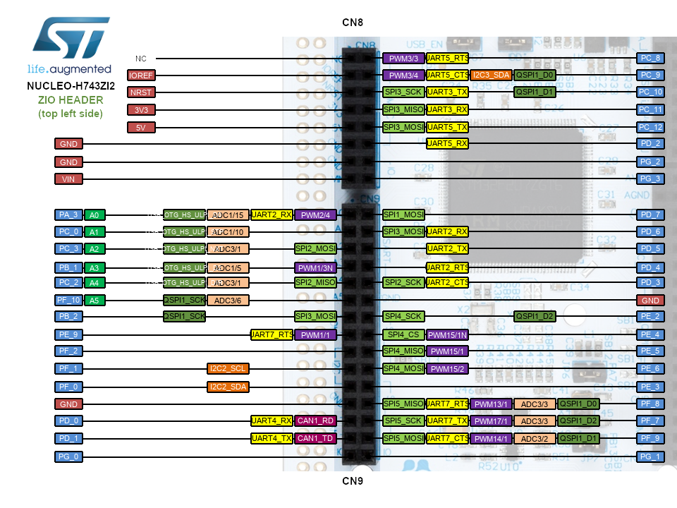 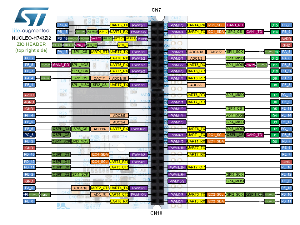 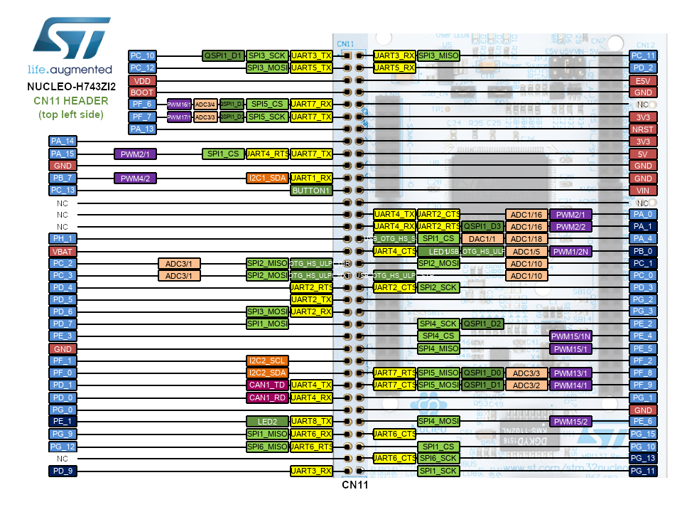 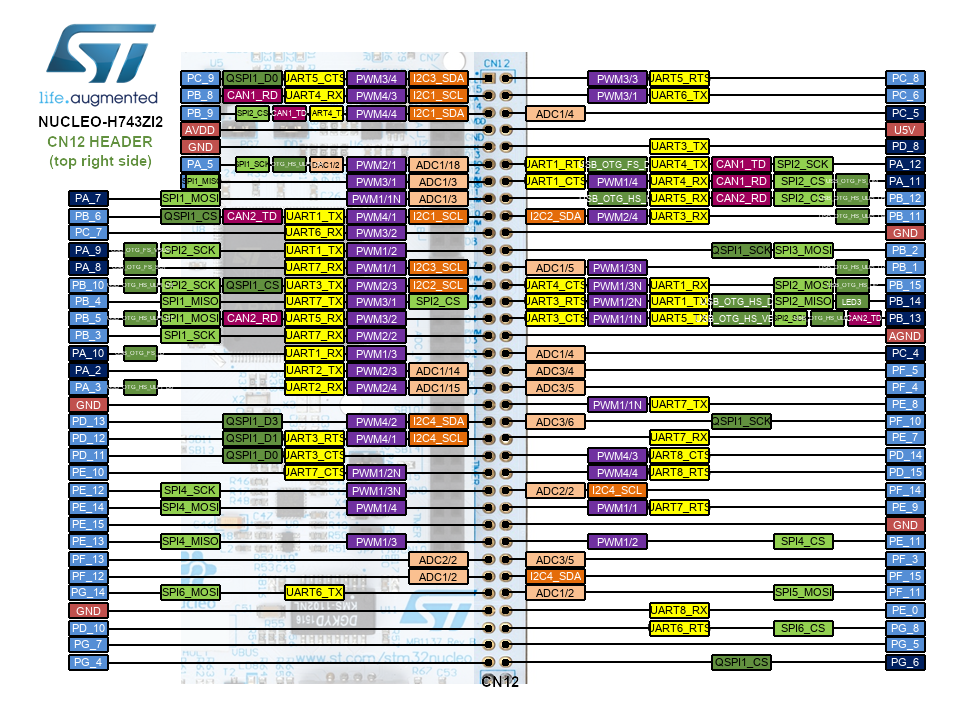 SCL D15, SDA D14 SCK D2, MO D4, MI D3, RX D0, TX D1The anlog pins can be used as digital pins too: A0 D16, A1 D17, A2 D18, A3 D19, A4 D20, A5 D21 Digital PinsRESET / JP1.16D0 / UART_RX / PB7 / CN10.16
D1 / UART_TX / PB6 / CN10.14
D2 / PG14 / CN10.12
D3 / PE13 / CN10.10
D4 / PE14 / CN10.8
D5 / PE11 / CN10.6
D6 / PE9 / CN10.4
D7 / PC13 / CN10.2
D8 / PF3 / CN7.20
D9 / PD15 / CN7.18
D10 / PD14 / CN7.16
D11 / MOSI / PB5 / CN7.14
D12 / MISO / PA6 / CN7.12
D13 / SCK / PA5 / CN7.10
D14 / SDA / PB9 / CN7.4D15 / SCL / PB8 / CN7.2Analog PinsA0 / D16 / PA3 / CN9.1
A1 / D17 / PC0 / CN9.3
A2 / D18 / PC3 / CN9.5
A3 / D19 / PB1 / CN9.7
A4 / D20 / PC2 / CN9.9
A5 / D21 / PF10 / CN9.11
SD Card / SDIO PinsSDIO_D0 / DATA_OUT / PC8 (internal) / CN8.2SDIO_D1 / DAT1 / PC9 (internal) / CN8.4SDIO_D2 / DAT2 / PC10 (internal) / CN8.6SDIO_D3 / CS / PC11 (internal) / CN8.8SDIO_CLK / SCLK /PC12 (internal) / CN8.10SDIO_CMD / DATA_IN / PD2 (internal) / CN8.12SD_DETECT / CARD_DETECT / PB12 (internal) / optional / CN7.7QSPIQS_CS / PG6 (external) / CN10.13QS_CLK / PB2 (external) / CN10.15QS_D3 / PD13 (external) / CN10.19QS_D1 / PD12 (external) / CN10.21QS_D0 / PD11 (external) / CN10.23QS_D2 / PE2 (external) / CN10.25USBUSB_DP / PA12USB_DM / PA11VCP UARTSTLK_VCP_TX / PG14 / ST-LINK VCP Rx
STLK_VCP_RX / PG9 / ST-LINK VCP Tx
 This work by Peter Schmid is licensed under a Creative Commons Attribution-ShareAlike 4.0 International License. \ No newline at end of file | ||||||||||||||||||||||||||||
View topic | History: r13 < r12 < r11 < r10 | More topic actions...
Ideas, requests, problems regarding TWiki? Send feedback