Board Support Package for the Flipper Zero (STM32WB55 MCU)
Intro
TBD


Board Support Words
Defaults: Digital port pins D0 to D4 are inputs with pull-up resistors.
rgbled!      ( rgb -- )  set the RGB led ($ff0000 red, $00ff00 green, $0000ff blue)
rgbled@      ( -- rgb )  get the RGB led ($ff0000 red, $00ff00 green, $0000ff blue)
wled!        ( u -- )    set the W (LCD backlight) led
wled@        ( -- u )    get the W (LCD backlight) led

switch1?     ( -- ? )    get switch1 (BACK button), closed=TRUE
switch2?     ( -- ? )    get switch2 (OK button), closed=TRUE
switch3?     ( -- ? )    get switch3 (RIGHT button), closed=TRUE
switch4?     ( -- ? )    get switch4 (LEFT), closed=TRUE
switch5?     ( -- ? )    get switch5 (UP button), closed=TRUE
switch6?     ( -- ? )    get switch6 (DOWN button), closed=TRUE

button       ( -- c )    wait for and fetch the pressed button (similar to the key word)
                         char b BACK, o OK, r RIGHT, l LEFT, u UP, d DOWN
button?      ( -- ? )    Is there a button press?

dport!       ( n -- )    set the digital output port (D0=bit0 .. D15=bit15).
dport@       ( -- n )    get the digital input/output port (D0=bit0 .. D15=bit15).
dpin!        ( n a -- )  set the digital output port pin (D0=0 .. D15=15)
dpin@        ( a -- n )  get the digital input/output port pin
dmod         ( u a -- )  set the pin mode: 0 in, 1 in pull-up, 2 in pull-down, 3 out push pull, 4 out open drain,
                                            5 out push pull PWM, 6 input capture, 7 output compare, 8 I2C

EXTImod      ( u a -- )  set for pin a (D2, D4, D7, D10) the EXTI mode u: 0 rising, 1 falling, 2 both edges, 3 none
EXTIwait     ( u a -- )  wait for EXTI interrupt on pin a (D2, D4, D7, D10), timeout u in [ms]

pwmpin!      ( u a -- )  set the digital output port pin a (D4=4, D11=11) to a PWM value u (0..1000). Default frequency is 1 kHz, TIMER1
pwmprescale  ( u --  )   Set the PWM prescale for TIMER1. 32 kHz / prescale, default 32 -> PWM frequency 1 kHz

ICOCprescale ( u -- )    set the input capture / output compare prescale for TIMER2. default 32 -> 32 MHz / 32 = 1 MHz, timer resolution 1 us
ICOCperiod!  ( u -- )    set the input capture / output compare (TIMER2) period. default $FFFFFFFF (4'294'967'295).
                         When the up counter reaches the period, the counter is set to 0.
                         For prescale 32 the maximum time is about 1 h 11 m
ICOCcount!   ( -- u )    set the input capture / output compare counter for TIMER2
ICOCcount@   ( u -- )    get the input capture / output compare counter for TIMER2
ICOCstart    ( -- )      start the ICOC period
ICOCstop     ( -- )      stop the ICOC period
OCmod        ( u a -- )  set for pin a (D0, D1, D5) the Output Compare mode u: 0 frozen, 1 active level on match, 2 inactive level on match,
                            3 toggle on match, 4 forced active, 5 forced inactive

OCstart      ( u a -- )  start the output compare mode for pin a with pulse u
OCstop       ( a -- )    stop output compare for pin a
ICstart      ( u -- )    start input capture u: 0 rising edge, 1 falling edge, 2 both edges
ICstop       ( -- )      stop input capture

waitperiod   ( -- )      wait for the end of the TIMER2 period
OCwait       ( a -- )    wait for the end of output capture on pin a
ICwait       ( u -- u )  wait for the end of input capture with timeout u, returns counter u

apin@        ( a -- u )  get the analog input port pin (A0 .. A2). Returns a 12 bit value (0..4095)
vref@        ( -- u )    get the Vref voltage in mV (rather the VDDA)
vbat@        ( -- u )    get the Vbat voltage in mV
CPUtemp@     ( -- u )    get CPU temperature in degree Celsius

I2Cput       ( a # u -- )     put a message with length u (count in bytes) from buffer at a to the I2C slave device u
I2Cget       ( a # u -- )     get a message with length u from I2C slave device to buffer at a
I2Cputget    ( a #1 #2 u -- ) put a message with length #1 from buffer at a to the I2C slave device u
                              and get a message with length #2 from device to buffer at a

SPIget       ( a # -- )       get a message with length # from SPI slave device to buffer at a
SPIput       ( a # -- )       put a message with length # from buffer at a to the SPI slave device
SPIputget    ( a #1 #2 -- )   put a message with length #1 from buffer at a to the SPI slave device
                              and get a message with length #2 from device to buffer at a
SPImutex     ( -- a )         get the SPI mutex address
Using the Digital Port Pins (Input and Output)
This example is very similar to the McForth#Knight_Rider program.dport! and dport@ set and get all 16 digital pins (D0 to D15) at once. You have to press the SW1 push button til D0 is set to cancel the operation.
3 0 dmod   \ set D0 to Output
3 1 dmod   \ set D1 to Output
3 2 dmod   \ set D2 to Output
3 3 dmod   \ set D3 to Output
3 4 dmod   \ set D4 to Output
3 5 dmod   \ set D5 to Output
3 6 dmod   \ set D6 to Output
3 7 dmod   \ set D7 to Output
: left ( -- )
  7 0 do
    dport@ shl dport!
    100 osDelay drop
  loop
;
|
: right ( -- )
  7 0 do
    dport@ shr dport!
    100 osDelay drop
  loop
;
|
: knightrider ( -- )
  1 dport!
  begin
    left right
    switch1? \ or key?
  until
  0 dport!
;
|
: left ( -- )
  7 0 do
    1 i dpin!
    100 osDelay drop
    0 i dpin!
  loop
;
|
: right ( -- )
  8 1 do
    1 8 i - dpin!
    100 osDelay drop
    0 8 i - dpin!
  loop
;
|
: knigthrider ( -- )
  begin
    left right
    switch1?
  until
  0 0 dpin!
;
|
Using the ADC (Analog Input Pins)
apin@ ( a -- u ) returns the ADC value (12 bit, 0 .. 4095) from one of the analog pins A0 to A5 (0 .. 5). Here I use the A0 to control the delay.
: left ( -- )
  7 0 do
    1 i dpin!
    0 apin@ 10 / osDelay drop  \ delay depends on A0
    0 i dpin!
  loop
;
|
: right ( -- )
  8 1 do
    1 8 i - dpin!
    0 apin@ 10 / osDelay drop  \ delay depends on A0
    0 8 i - dpin!
  loop
;
|
left or right word takes about 125 us, the knightrider loop about 50 us (no osDelay). Pretty fast for my opinion.
CH1 yellow: D0 pinCH2 blue: D1 pin

Using the PWM (Analog Output Pins)
Only two port pins are supported so far. The 16 bit TIMER1 is used for the timebase, time resolution is 1 us (32 MHz SysClk divided by 32). The PWM scale is from 0 (0 % duty cycle) to 1000 (100 % duty cycle), this results in a PWM frequency of 1 kHz. If you need higher PWM frequencies, decrease the divider and/or the scale. PWM port pins: D11 (TIM1CH1), D4 (TIM1CH2) Simple test program to set brightness of a LED on pin D3 with a potentiometer on A0. Default PWM frequency is 1 kHz (prescaler set to 32). You can set the prescale with the wordpwmprescale from 32 kHz (value 1) down to 0.5 Hz (64000).
5 3 dmod   \ set D3 to PWM

: pwm ( -- )
  begin
    0 apin@  4 /  3 pwmpin!
    10 osDelay drop
    switch1?
  until
;
Using Input Capture and Output Compare
Time Base
Default timer resolution is 1 us. The 32 bit TIMER2 is used as time base for Input Capture / Output Compare. For a 5 s period 5'000'000 cycles are needed. All channels (input capture / output compare) use the same time base.
: period ( -- )
  5000000 ICOCperiod! \ 5 s period
  ICOCstart
  begin
     waitperiod
     cr .time
  key? until
  key drop
;
Output Compare
Only one port pin (D9) is supported so far.
: oc-toggle ( -- )
  5000000 ICOCperiod! \ 5 s period
  ICOCstart
  3 9 OCmod  1000000 0 OCstart \ toggle D9 after 1 s
  begin
     waitperiod
     cr .time
  key? until
  key drop
;
When you abort (hit any key) the program, the timer still runs and controls the port pins. To stop the port pins:
0 OCstop 1 OCstop 5 OCstopOr change the prescale to make it faster or slower:
1 ICOCprescale
Input Capture
This sample program measures the time between the edges on port A2. if no event occurs within 2 seconds, "timeout" is issued. Hit any key to abort program.
: ic-test ( -- )
  6 2 dmod \ input capture on A2
  ICOCstart
  2 ICstart  \ both edges
  ICOCcount@ ( -- count )
  begin
    2000 \ 2 s timeout
    ICwait ( -- old-capture capture )
    cr
    dup 0= if
      ." timeout" drop
    else
      dup rot ( -- capture capture old-capture )
      - 1000 / . ." ms"
    then
  key? until
  key drop
  drop
  ICstop
;
Pinouts
Power
| Signal name | STM32WB55 pin | Comment |
|---|---|---|
| PERIPH_POWER | PA3 | LM3281 Enable, Low for shutdown |
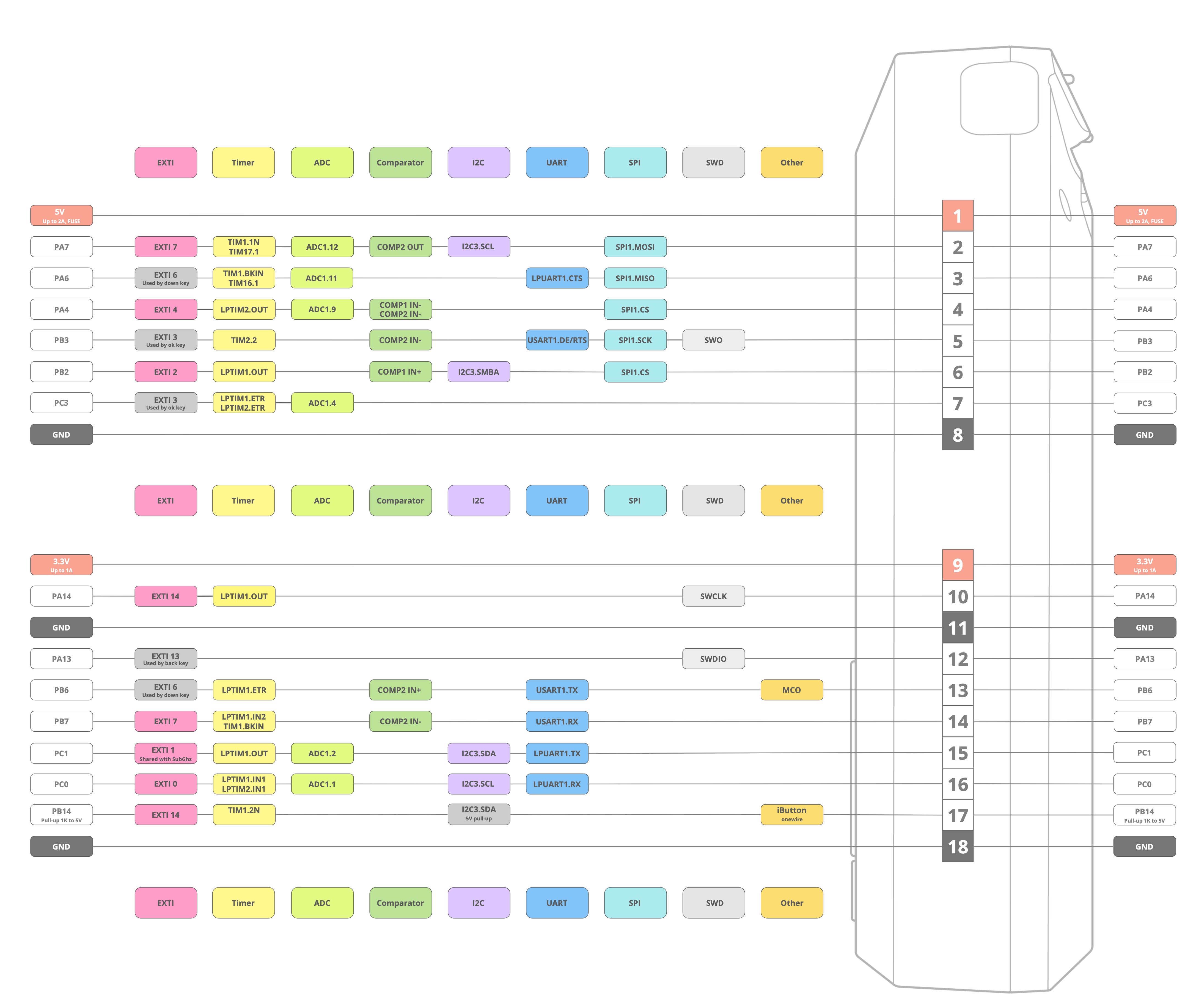
GPIO Ports

| Pin | Label | STM32WB55 pin | Arduino | Alternate Functions |
|---|---|---|---|---|
| 1 | +5V | |||
| 2 | A7 | PA7 | D11 | SPI1_MOSI, TIM1_CH1 (PWM) |
| 3 | A6 | PA6 | D12 | SPI1_MISO |
| 4 | A4 | PA4 | D10 | SPI1_CS |
| 5 | B3 | PB3 | D13 | SPI1_CLK, SWO |
| 6 | B2 | PB2 | D9 | TIM2_CH2 (output capture) |
| 7 | C3 | PC3 | A2(D18) | |
| 8 | GND | |||
| 9 | 3V3 | |||
| 10 | SWC | PA14 | D3 | SWCLK |
| 11 | GND | |||
| 12 | SIO | PA13 | D2 | SWDIO |
| 13 | TX | PB6 | D1 | |
| 14 | RX | PB7 | D0 | |
| 15 | C1 | PC1 | A1 (D17) | I2C3_SDA |
| 16 | C0 | PC0 | A0 (D16) | I2C3_SCL |
| 17 | 1W | PB14 | D4 | TIM1_CH2 (PWM) |
| 18 | GND |
JTAG/SWD Adaptor
| JTAG Pin | JTAG STM 14pin | Flipper Pin | STLINK-V3MINI | Description |
|---|---|---|---|---|
| 1 | NC | |||
| 2 | NC | |||
| 1 | 3 | 9 | 30 (right) | VDD |
| 2 | 4 | 12 | 4 (left) | SWDIO |
| 3 | 5 | 8 | 8 (left) | GND |
| 4 | 6 | 10 | 13 (left) | SWCLK |
| 5 | 7 | GND | ||
| 6 | 8 | 5 | 6 (left) | SWO |
| 7 | 9 | NC | ||
| 8 | 10 | NC | ||
| 9 | 11 | 11 | 5 (left) | GND_DETECT |
| 10 | 12 | - | 31 (right) | NRST |
| 13 | 14 | 15 (left) | VCP_RX Target | |
| 14 | 13 | 12 (left) | VCP_TX Target |
Push Buttons
| Signal name | STM32WB55 pin | Comment | Numbering |
|---|---|---|---|
| BUTTON_BACK | PC13 | RESET, WKUP2 | 1 |
| BUTTON_OK | PH3 | BOOTP | 2 |
| BUTTON_RIGHT | PB12 | 3 | |
| BUTTON_LEFT | PB11 | RESET | 4 |
| BUTTON_UP | PB10 | 5 | |
| BUTTON_DOWN | PC6 | 6 |
RGB LED, LCD Backlight LED
| Signal name | STM32WB55 pin | Comment |
|---|---|---|
| IC2_SCL | PA9 | |
| IC2_SDA | PA10 |
- I2C Address write 60h, read 61h.
- PWM frequency is either 256 Hz or 558 Hz.
- max. 25.5 mA, 100 uA steps
furi_hal_light.h
#define LED_CURRENT_RED 50
#define LED_CURRENT_GREEN 50
#define LED_CURRENT_BLUE 50
#define LED_CURRENT_WHITE 150
UART VCP ST-LINK
| Signal name | STM32WB55 pin | Comment |
|---|---|---|
| UART_TX | PB6 | USART1_TX |
| UART_RX | PB7 | USART1_RX |
SPI LCD Display
Sitronix ST7567S| Signal name | STM32W555 pin | Comment |
|---|---|---|
| DISPLAY_RST | PB0 | |
| DISPLAY_DI | PB1 | |
| DISPLAY_CS | PC11 | CS |
| SPI_D_MOSI | PB15 | SPI2_MOSI |
| SPI_D_SCK | PD1 | SPI2_SCK |
| LCD_LED | PC9 |
microSD Adapter (SD Drive)
| Signal name | STM32W555 pin | Comment |
|---|---|---|
| SD_CS | PC12 | Chip Select |
| SD_CD | PC10 | Card Detect |
| SPI_D_MOSI | PB15 | SPI2_MOSI |
| SPI_D_MISO | PC2 | SPI2_MISO |
| SPI_D_SCK | PD1 | SPI2_SCK |
LIPO Charger, Fuel Gauge
- BQ25896RTWR
 Charger, 0x6b (1101011B + R/W)
- BQ27220YZFR Fuel gauge, 0x55 (1010101 + R/W),
| Signal name | STM32WB55 pin | Comment |
|---|---|---|
| IC2_SCL | PA9 | |
| IC2_SDA | PA10 | |
| PWR_INT | - |
Vibro and Speaker
| Signal name | STM32WB55 pin | Comment |
|---|---|---|
| SPEAKER | PB8 | TIM16CH1, TIM1CH2N |
| VIBRO | PA8 |
NFC
ST25R3916
This work by Peter Schmid is licensed under a Creative Commons Attribution-ShareAlike 4.0 International License.


| I | Attachment | History | Action | Size | Date | Who | Comment |
|---|---|---|---|---|---|---|---|
| |
flipper-gpio.jpg | r1 | manage | 745.7 K | 2023-10-28 - 20:21 | PeterSchmid | |
| |
flipper-header.jpg | r1 | manage | 50.9 K | 2023-11-11 - 19:49 | PeterSchmid | |
| |
flipper-stlink-2.jpg | r1 | manage | 752.0 K | 2023-11-11 - 19:34 | PeterSchmid | |
| |
flipper-stlink.jpg | r1 | manage | 357.3 K | 2023-11-11 - 19:34 | PeterSchmid |
Topic revision: r16 - 2023-12-14 - PeterSchmid

|
|
|
|
Ideas, requests, problems regarding TWiki? Send feedback